
Three ST3020 serial-bus servos arrived a couple of weeks ago, and the plan was simple on paper: swap them in for the hexapod’s current DS3235 legs. It did not stay simple, but it landed somewhere better than where it started.
Why change the servos at all
The short version: a whole separate investigation (the gait-rework
branch) concluded the hexapod’s walking problems weren’t really about the
gait pattern — they were about the actuation layer. Open-loop 50 Hz
position setpoints, no velocity profiling, no feedback. Bolting on bigger,
stronger servos didn’t fix it either; the demand causing the trouble is
dynamic (touchdown impact, streaming position steps), not a raw
torque ceiling.
Serial-bus servos like the ST3020 report back position, speed, and load over a shared UART bus. That’s the actual thing missing — this redesign is a feedback-and-control play, not a horsepower upgrade.
First attempt: a coxa that couldn’t actually be assembled
The first coxa design bolted the femur servo into a fully enclosed cradle — walls on every side, holes for the mounting bosses. It looked right in CAD. It was also physically impossible to build: the femur servo has an output horn on one face and an idler boss on the opposite face, and a box with walls on both sides has no way to let either one in. You can’t post a solid servo body through a hole smaller than itself.
There was a detour before that got noticed — an attempt to make the coxa look “organic,” bone-like, via a Blender skin-and-voxel pipeline. It actually worked (watertight, printable), but it wasn’t the right direction, and it got shelved in favor of fixing the actual mechanical problem.
The fix: stop enclosing the servos, grip the horns instead
The working design that came out of this treats every joint the same way: an open double-hub yoke that bolts to both horns of a servo, with nothing but open air where the servo’s body sits. The body just drops in from the side. No wall ever has to trap it.
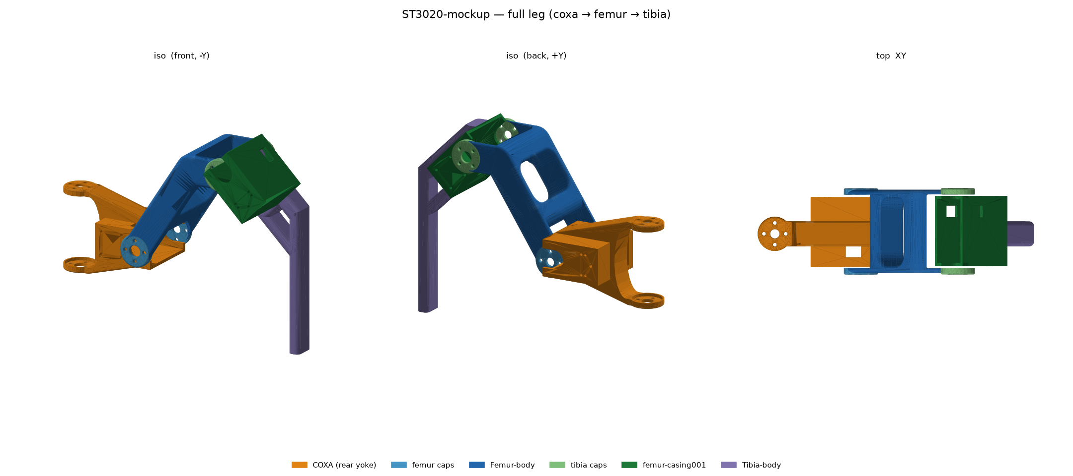
The femur link in particular is a nice double-yoke — open hubs at both ends, one gripping the femur servo’s horns (driving the coxa–femur joint), the other gripping the tibia servo’s horns (driving the knee). The servo bodies themselves live in open-faced pockets on the neighboring links instead.
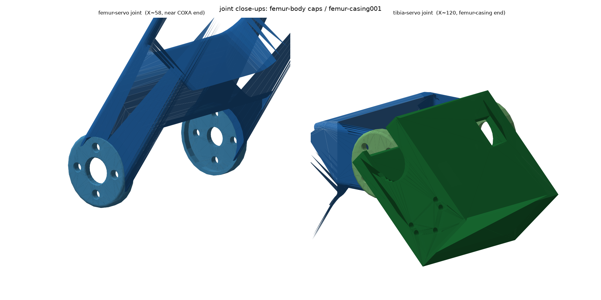
Checking the fit for real, not by eye
“Looks right in the render” isn’t good enough after the first design fooled
everyone that way. Every joint got checked against the servo’s actual
imported CAD geometry with a real boolean intersection (Blender’s newer
MANIFOLD solver, which turned out to be far more reliable for
this than it had any right to be) — computing the exact overlap volume
between the printed part and the servo, not just staring at a render.
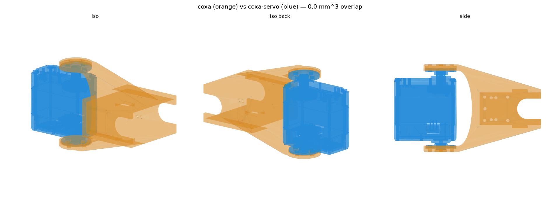
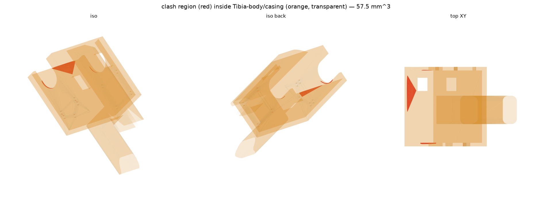
Three of four joints came back clean immediately. The fourth — the tibia servo against its casing — did not:
From CAD to a leg that thinks it’s a robot
Once the geometry held up, the next step was making it usable outside FreeCAD: real inverse-kinematics numbers and a URDF that loads in RViz2.
| Value | New (ST3020 leg) | Old (current robot) |
|---|---|---|
| Coxa length | 55.40 mm | 44.0 mm |
| Femur length | 87.15 mm | 80.0 mm |
| Tibia length | 126.51 mm (no foot pad yet) | 132.3 mm |
Those came straight out of the mockup’s exact joint-axis geometry — measured from the real circular bore edges in the BREP model, not eyeballed off a render.
The URDF took it a step further: every link’s mass and inertia is computed from the real FreeCAD solids (volume, center of mass, full inertia tensor), combined with each servo’s actual measured weight — 97 grams, confirmed against a live product page, since the spec sheet on file didn’t have it — added to whichever link’s pocket actually cradles that servo’s body. Joint effort and velocity limits are the servo’s real numbers too: 2.45 N·m stall torque, 6.3 rad/s no-load speed. It’s not just a shape anymore; it’s a model that carries real numbers.
Along the way, two genuinely dumb bugs: passing a URDF throughros2 run ... -p robot_description:="$(cat file)"breaks ROS2’s command-line parser the moment it hits a multi-line XML comment (a launch file sidesteps this entirely) — and it turns out--inside an XML comment is invalid, full stop, which is exactly the kind of thing you only find out after writing three paragraphs of comment explaining your own math.
What’s still open
- No foot pad on the tibia yet — the leg currently ends in a blunt shaft.
- The femur-at-servo stress riser that’s broken every leg so far hasn’t been addressed in this mockup yet.
- Bus voltage (7.4 V vs. 12 V) and the resulting torque budget still need bench measurement, not estimates.
- The ROS2 driver for the Feetech STS/SCS bus protocol doesn’t exist yet — right now this is geometry and math, not a moving leg.
Next up is closing those out, starting with a real printed test fit.